Step 4 Teaching Positions
Teaching the Machine (Setting the Marking Position)
Teaching the machine establishes the relationship between the marking layout (software) and the physical part positioned under the marking head. The layout represents the machine’s printable area—not the actual part. Teaching synchronizes the layout coordinates with the real-world X and Y motor positions so the mark is placed correctly on the material.

Preparation
- Ensure your layout is open and all required entities (text, logos, etc.) are placed in the layout.
- Each entity displays a green reference point:
- Bottom-left corner by default.
- Center point if the center function was used.
This reference point determines the entity’s position on the material. If the green
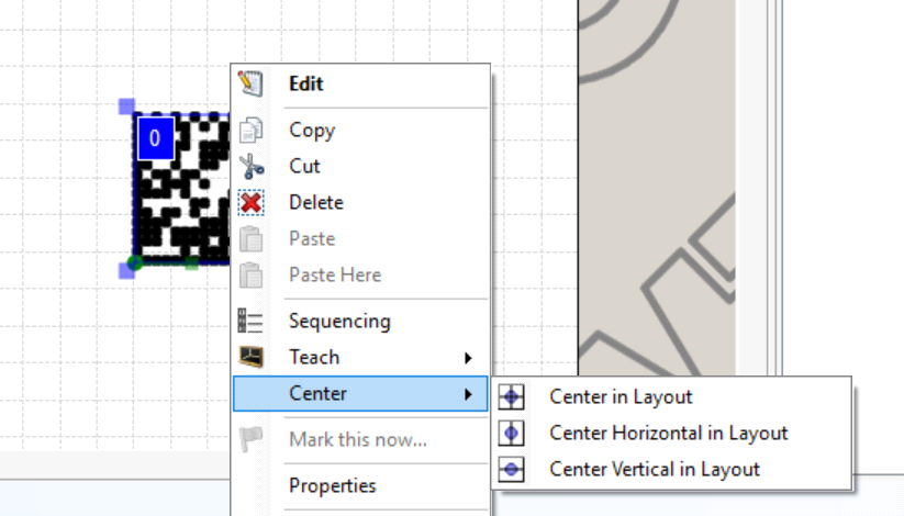
reference point is located at the center of the entity, and the marking head is taught to that location, the center of the entity will be placed at that exact position on the material.
By default, marking starts from the bottom-left corner of the entity unless otherwise configured.

Manual Teaching Procedure
1. Open Manual Control
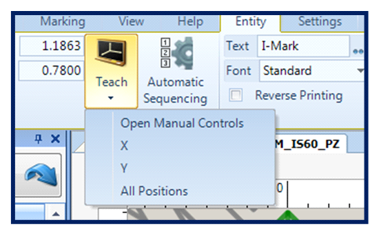
- Double-click the entity in the layout to activate the Entity tab in the ribbon.
- Click the Teach icon.
- From the dropdown menu, select Manual Control.
This opens the manual jogging controls for the marking head, using the arrows.
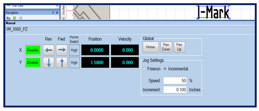

2. Jog the Marking Head to the Desired Location
Using the X and Y axis controls:
- Jog the X-axis until the marking pin is positioned over the desired starting point on the part.
- Jog the Y-axis to align vertically with the intended marking location.
Continue adjusting until the marking pin is precisely positioned where the first character (bottom-left reference point) should begin on the part.

3. Apply the Taught Position
Once the marking head is correctly positioned:
- Return to the Entity tab.
- Click the Teach icon again.
- Select All Positions from the dropdown menu.
This action:
- Captures the current X-Y motor position.
- Updates the entity’s position within the layout.
- Synchronizes the layout coordinates with the physical part location.
You will see the entity shift within the layout grid to reflect its newly taught position.

Result
The entity is now properly aligned between:
- The layout coordinate system (software)
- The machine’s motor positions (hardware)
- The physical part on the fixture
When the marking cycle runs, the text or entity will begin at the taught location on the material.

Key Notes
- The layout is a representation of the printable field—not the physical part.
- The reference point sets where the entity will appear on the material, with the green point marking the entity’s reference point.
- Always verify part placement before teaching.
- If the part or fixture position changes, the entity must be re-taught.
This process ensures accurate and repeatable marking placement.
Adjusting Speed
Setting Global and Entity-Specific Speeds
The I-Mark software allows different marking speeds to be assigned to individual entities within a layout. This feature enables optimization of both cycle time and mark quality.
For example, in a layout containing standard text and a 2D Data Matrix code:
- Text can be marked at a higher speed to reduce cycle time.
- The Data Matrix can be marked at a lower speed to improve clarity and scanner readability.

Global Speed
The Global Speed defines the default marking speed for the entire layout.
All entities will run at this speed unless an entity-specific speed is applied.
To Set the Global Speed
- Click on the layout background (not on an entity).
- Access the speed setting in the layout properties.
- Adjust the speed value as required.
This speed will apply to all entities that have the Global option enabled.

Entity-Specific Speed
An entity-specific speed overrides the Global Speed for that particular object.
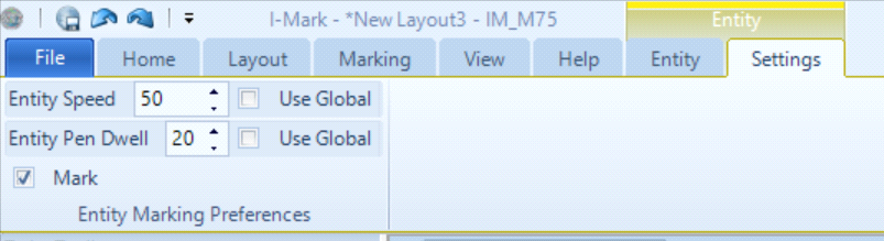
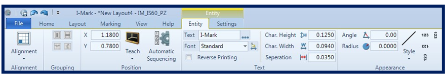
To Set a Speed for a Specific Entity
- Select the desired entity in the layout.
- Open the Settings tab in the Ribbon menu.
- Uncheck the Global option.
- Enter the required speed value.
The selected entity will now operate at the specified speed while other entities continue to follow the Global Speed (unless individually overridden).

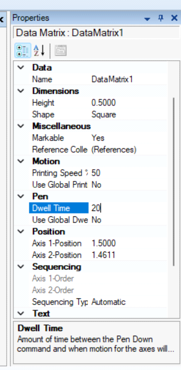
Entity Dwell
The Entity Dwell property adds a controlled pause after each movement while drawing a character. This can be adjusted in the properties function of the I-Mark software.
Purpose of Entity Dwell
This setting is useful when:
- Operating at high marking speeds.
- Portions of characters appear incomplete.
- Mark quality begins to degrade due to insufficient pin impact time.
By increasing dwell:
- The marking head pauses briefly after each movement.
- Character definition improves.
- Mark consistency is enhanced.

Operational Considerations
- Use higher speeds for simple text to reduce cycle time.
- Use lower speeds for complex geometries (e.g., 2D Data Matrix codes).
- Increase dwell if characters appear light, broken, or inconsistent.
- Avoid excessive dwell, as it will increase total cycle time.
Proper use of Global Speed, Entity-Specific Speed, and Entity Dwell allows optimization of both productivity and marking quality.
Download and Save
Downloading and Saving the Layout to the Controller
After defining all marking parameters—such as coordinates and speed—the layout must be downloaded to the controller before production marking begins.
Although live streaming is possible from the active marking window, it is best practice to download and save the layout to the controller to ensure stability and repeatability.

Access the Controller Page
- Select your machine in the Navigation pane.
- Open the active controller window.
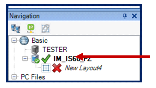
In the Navigation pane:
- A green check mark indicates the layout and controller are synchronized.
- A red X indicates changes have not yet been downloaded.

Download and Save the Layout
- From the controller page, click the Download button.
- The system will prompt:
- “Do you want to save all fields before downloading?”
- Select Yes.
This ensures that:
- Speed settings
- Taught coordinates
- Entity-specific parameters
are saved prior to transfer.

Rename and Save the Layout
After confirming the save:
- A Save Layout As dialog will appear.
- Enter the desired layout name.
- Click Save.
The layout will now begin downloading to the controller memory.

Download Process and Status Indicators
During the download:
- The marking window status will display Not Initialized.
- The controller transfers the layout and configuration data.
- After completion, the machine will perform a home routine.
Once complete:
- The status banner will display Ready.
- The Navigation pane will show a green check mark next to both:
- The layout
- The machine
This confirms that:
- The layout was successfully downloaded.
- The controller and software are synchronized.
- The system is ready for marking operations.

Best Practice
Always download and save the layout before production marking to ensure:
- Correct parameter retention
- Proper controller synchronization
- Reliable machine operation
Consequently, your I-Mark should automatically prompt you to save your layout.
Created with the Personal Edition of HelpNDoc: Step-by-Step Guide: How to Turn Your Word Document into an eBook