Ethernet IP
Setup I-Mark for Ethernet/IP Communication
When the EtherNet/IP Mode has been activated, the I-Mark Controller will be constantly monitoring a Control Register which allows you to remotely control the marking machine over EtherNet/IP. Similarly, the I-Mark controller will be updating a local Register at a very high rate with a Bitwise Value of the Machine’s status. The I-Mark software contains a dialog which allows the user to map what standard controller functions you’d like to the available bits within the Control and Status Bytes.
The following is an instructional document which will help you in setting up the I-Mark controller for EtherNet/IP Mode.
Once connected to the controller through the I-Mark Software, the controller will show up under the Navigation pane on the lower left side of the software. You can double click on controller listed in here or if you select it, the Ribbon menu across the top will change to this controller specifically and you can select “Open Marking Machine”. With this screen you can modify the parameters of the machine as well as get the full status and live feed of what the machine is doing.
1. With the ribbon still highlighted on your controller page, there is an icon which looks like a Green and Red arrow opposing each other….

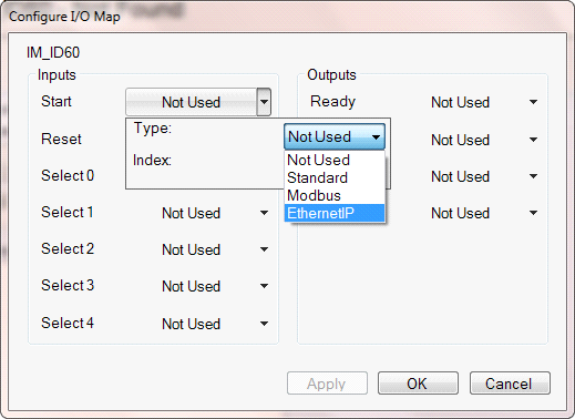
This button will open a dialog to allow you to configure the I/O’s of this controller.
This dialog will allow you to map the function listed to the left with the desired I/O index number and medium you would like to control it with. So for your configuration, you are going to go through each of these items and change their “Type” to Ethernet/IP and then make sure the index number below it is unique.
A basic setup should look like this chart here.
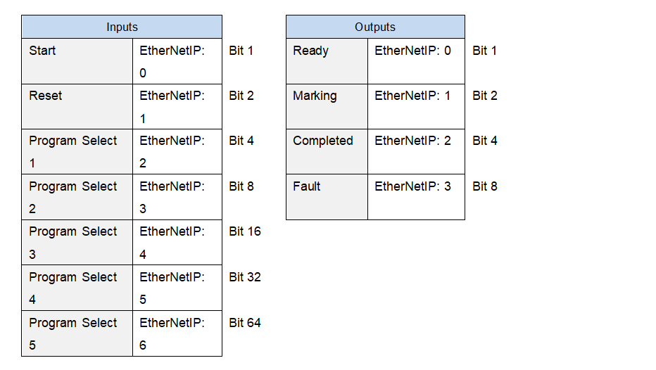
- Once you’ve configured it to be this way, press OK to apply and save this configuration to the workspace.
Step 2: Create a Layout with EtherNet/IP placeholder
- Go back to the Home tab and click “Create New Layout”. It will ask you what type of machine you want to create a layout for, if you’re directly connected to the machine there will only be 1 listed there (IM_ID60) just select this and click OK.

- Now you can see the Layout which appears to look like a grid, this is the physical marking window for the machine. To add a new text object which will print data received from the PLC over Ethernet/IP, click on the “Layout” tab at the top and single click on the button which says “Text”.
This button will drop a text entity into the center of the layout which reads simply “Text”. You modify this entity by double clicking on it which opens up a new dialog for editing the text entity. Delete the sample “Text” in the top field and then look down at the different codes available for dynamic data. One of the codes is labeled “Placeholder Text (Register/Ethernet/IP)”. You can click directly on this text or type in %p0 to the Text to Mark field as shown here.
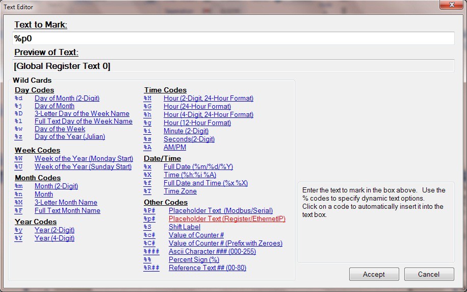
Now press Accept to apply the change to the Text entity. The text within the layout will say “Global Register Text 0" as this is just a simulation to illustrate that we are waiting for data to appear in order to mark it here because the register at this time is empty.
Step 3: Assign Layout to the controller.
- Click directly on the layout to activate the layout tab on the ribbon,
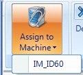
- Click on the button labeled "Assign to Machine"
- Click on the machine listed below this button which corresponds to the name of the machine you're currently working with. This will assign the currently layout to this machine so when a download occurs it will synchronize.
- Save the Layout by going to the "Home" tab and select "Save Layout"
Step 4: Set Layout as active layout for marking.

- Click the tab on the toolbar named after the controller you are working on. On this ribbon will be a button called "Layouts" click it
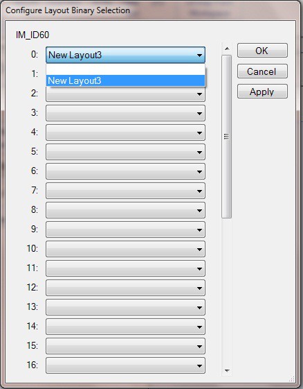
- Clicking this button will open up a dialog for you to assign layouts to a specific binary assignment. Set the layout you just created as the
Step 5: Save and download the configuration to the controller.
- Navigate to the Setup and Control tab within the Controller Page.
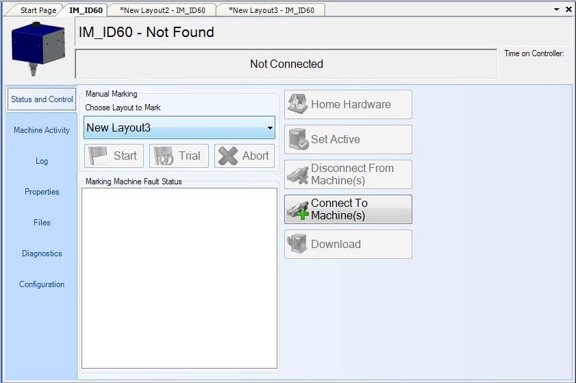
- Click on the Download button to save all of your Layouts and configuration to the controller’s memory.
- After the progress is completed, you may now disconnect from I-Mark
Created with the Personal Edition of HelpNDoc: Free CHM Help documentation generator