Using the Rotator
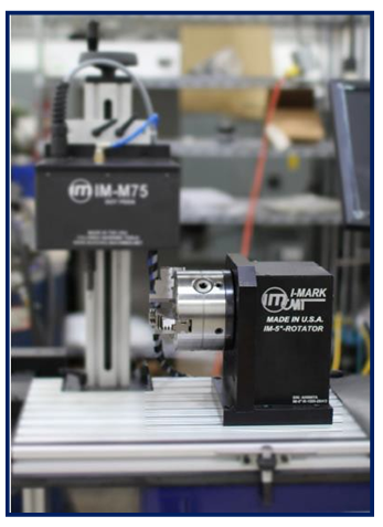
Creating a layout with the Rotator enabled.
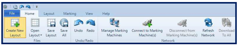
From the “Home” Menu select the “Create New Layout” button in the software.
On the “Create Layout” dialog choose your marker type from the list on the left and then on the right side of the screen. Choose the Axis configuration whose Axis in Parenthesis contain X and A.
NOTE: The axis within the parenthesis will be the two designated axis used for the drawing of the layout. All additional axis listed in the configuration will be available as positional axis only.
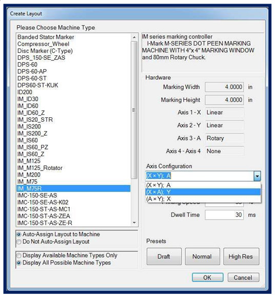
After you’ve selected a configuration, whose axis is a rotary type (A in this case), the dia- log will show a hidden field for the Part Diameter. This data in this field must be entered correctly to ensure that the scaling of the marking around the circumference of the part is accurate.
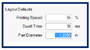
NOTE: If your part has multiple surfaces with varying diameters, the diameter at or closest to the desired marking location should be entered here.
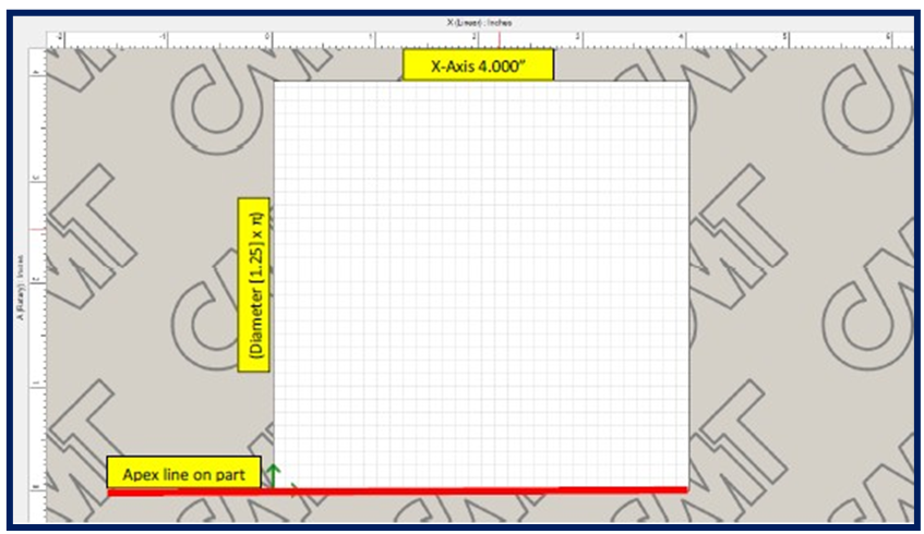
This is how the layout form will look if you’ve entered the same values I have in this example.
Horizontally is the X-axis and the vertical axis of this 2D layout is the A-axis. Its dimensions were calculated off the know X-axis travel distance of 4” and the calculated value of the part circumference (diameter [1.25] x π) = 3.9267 or roughly a 4x4 grid.
The bottom horizontal line of the grid represents the Apex of your part or the 12 o’clock position. This position must be taught for the Y-axis to ensure that the program will begin marking directly over top of the part.
Start by adding a text entity to your part. The program will drop the text automatically into the center of the layout grid.
Now located along the bottom of your software window is a tab named “Manual”. Move your cursor overtop of this tab to enable it to slide-out. This tab will allow us to jog the physical axis on the machine in order to teach the current position of the mark- ing axis to the text or any other desired entities in the program.
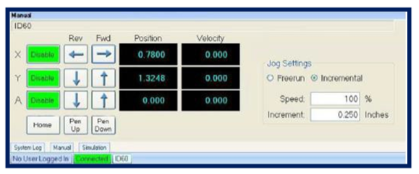
Jog the X-axis → until the marking pin is over top of the marking area you’re desiring to mark. Then jog the Y-axis ↓ to bring the pin directly overtop at the Apex or 12 o’clock position of the part.
Then when the pin is directly over top of the desired marking surface, select your text entity tab on the marking layout and right-click on it to show the
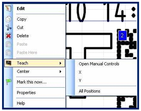
context menu.
Select “Teach → All Positions”.
After setting the position of the text to be equal to the current position of the marking axis, you’ll see that the text on the grid has moved to the relative position of the axis.
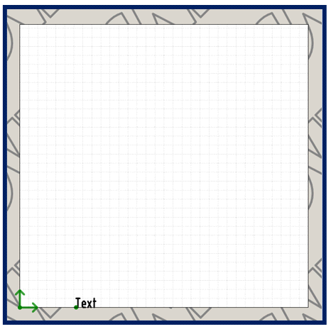
The current position is X = .7800, Y = 1.3248, A = 0.000
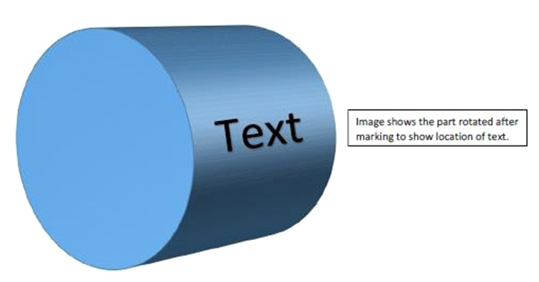
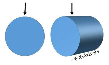
With the text in this current orientation moving horizontally, the marking head will rotate the part only slightly to draw the vertical motions of the character Height and the X- axis will move to draw the horizontal motions of the character Width. This will result in the marking along the part as such.
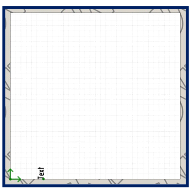
If you flip the orientation of the text entity to be written vertically as shown here then the marking will occur around the part using the A-Axis for the majority of the motion drawing the horizontal movement of the character Width and the X-axis will move small motions drawing the vertical height of the character Height.
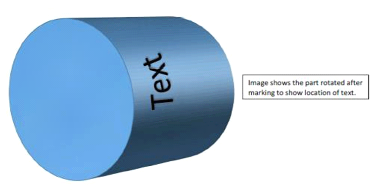
The resulting mark from this orientation will be as such.
Finally to do multiple text entities, just ensure that each one following the initial has the exact same Y-axis coordinate to make sure that the pin stays directly over top of the part.
Created with the Personal Edition of HelpNDoc: Maximize Your Documentation Capabilities with a Help Authoring Tool