Connections
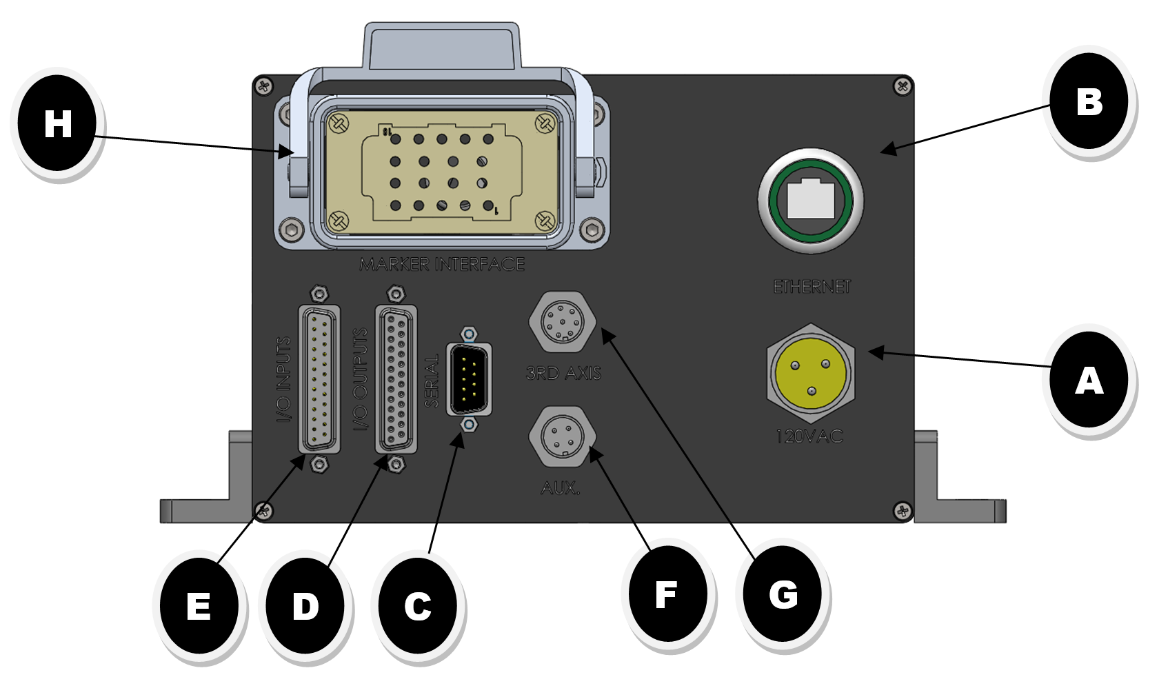
TABLE 1.0
|
ITEM |
DESCRIPTION |
TABLE |
|
A |
POWER CONNECTOR |
1.1 |
|
B |
ETHERNET CONNECTION |
1.2 |
|
C |
SERIAL DATA PORT |
1.3 |
|
D |
I/O OUTPUT CONNECTION PORT |
1.4 |
|
E |
I/O INPUT CONNECTION PORT |
1.5 |
|
F |
AUX. OUTPUT CONNECTOR (RESERVED) |
CONTACT FACTORY |
|
G |
Z-AXIS CONNECTOR (OPTIONAL) |
CONTACT FACTORY |
|
H |
MARKING HEAD INTERFACE CONNECTION |
CONTACT FACTORY |
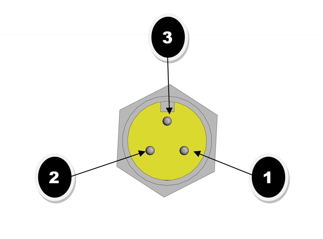
TABLE 1.1 POWER CONNECTOR
|
PIN |
CONNECTION |
|
1 |
LINE |
|
2 |
NEUTRAL |
|
3 |
GROUND |
|
NOTE: The I-Mark Series-2 Controller Requires 120vac power and may draw up to 7.2a depending on the marking head you are controlling. |
|
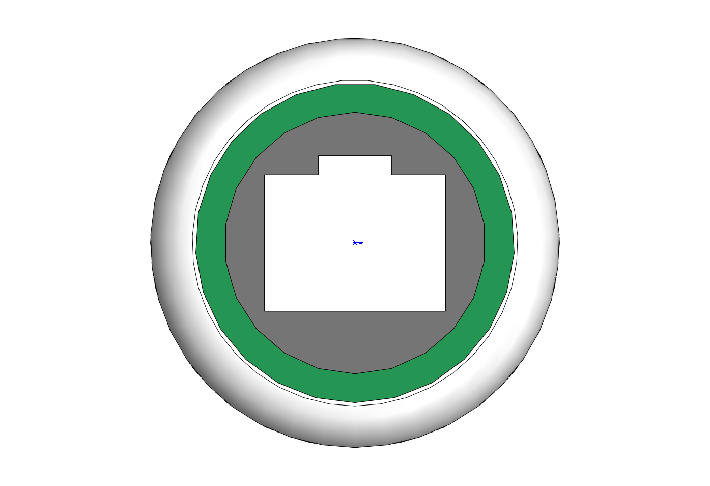
TABLE 1.2 ETHERNET CONNECTION
|
PIN |
DESCRIPTION |
|
1 |
ORANGE PAIR-2 |
|
2 |
|
|
3 |
GREEN PAIR-3 |
|
4 |
|
|
5 |
|
|
6 |
|
|
7 |
BROWN PAIR-4 |
|
8 |
Note: The I-Mark Control can operate using a Static IP address or using DHCP mode. When connecting to the I-Mark control via a switch or network you should use a standard CAT5e cable. If connecting the I-Mark control directly to a PC or laptop you will need to use a CAT5e crossover cable.
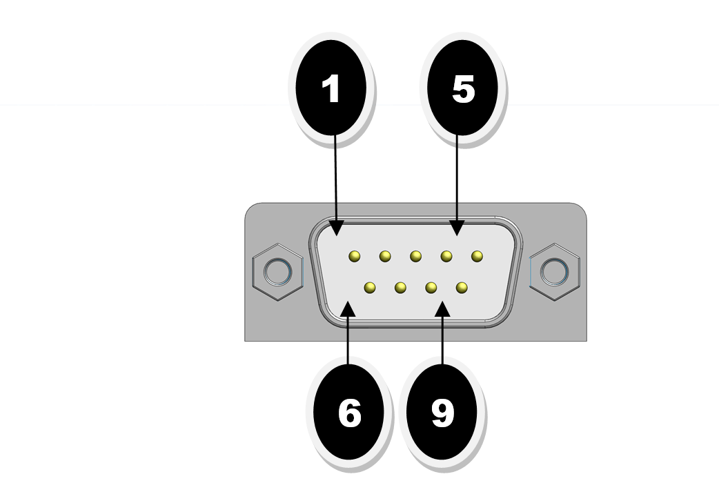
TABLE 1.3 SERIAL DATA PORT
|
PIN |
RS232 |
PARAMETERS |
|
|
1 |
DCD |
BAUDRATE |
115200 |
|
2 |
RxD |
FLOW CONTROL |
NONE |
|
3 |
TxD |
PARITY |
NONE |
|
4 |
DTR |
DATA BITS |
8 |
|
5 |
GND |
STOP BIT |
1 |
|
6 |
DSR |
NOTE: SEE EXAMPLE BELOW FOR SAMPLE STRING FORMAT. |
|
|
7 |
RTS |
||
|
8 |
CTS |
||
STRING FORMAT FOR SENDING ASCII DATA TO I-Mark PLACEHOLDER
NOTE: YOU CAN EDIT STRING CONFIGURATION IN I-MARK Config Tab
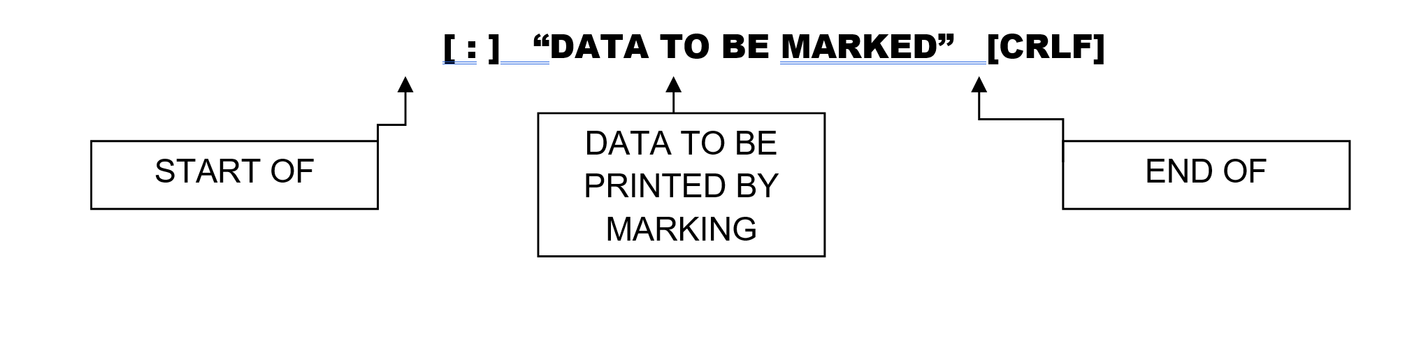
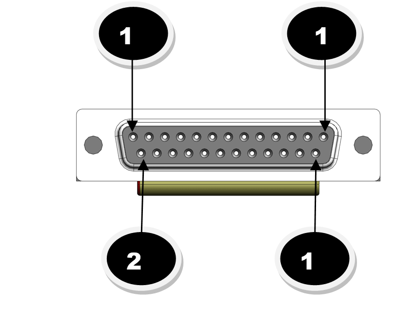
TABLE 1.4 I/O OUTPUT CONNECTIONS
|
PIN |
DESCRIPTION |
|
1 |
[24VDC] Common (Customer to supply.) |
|
2 |
[0VDC] Common (Customer to supply.) |
|
3 |
READY |
|
4 |
MARKING |
|
5 |
CYCLE COMPLETE |
|
6 |
FAULTED |
|
7 |
USER OUTPUT (programmable) |
|
8 |
USER OUTPUT (programmable) |
|
9 |
USER OUTPUT (programmable) |
|
10 |
USER OUTPUT (programmable) |
|
11 |
AUX. [ 24VDC ] (.5a MAX) |
|
12 |
AUX [ 0VDC ] (.5a MAX) |
|
13-25 |
RESERVED |
|
Note: 80ma max draw per output |
|
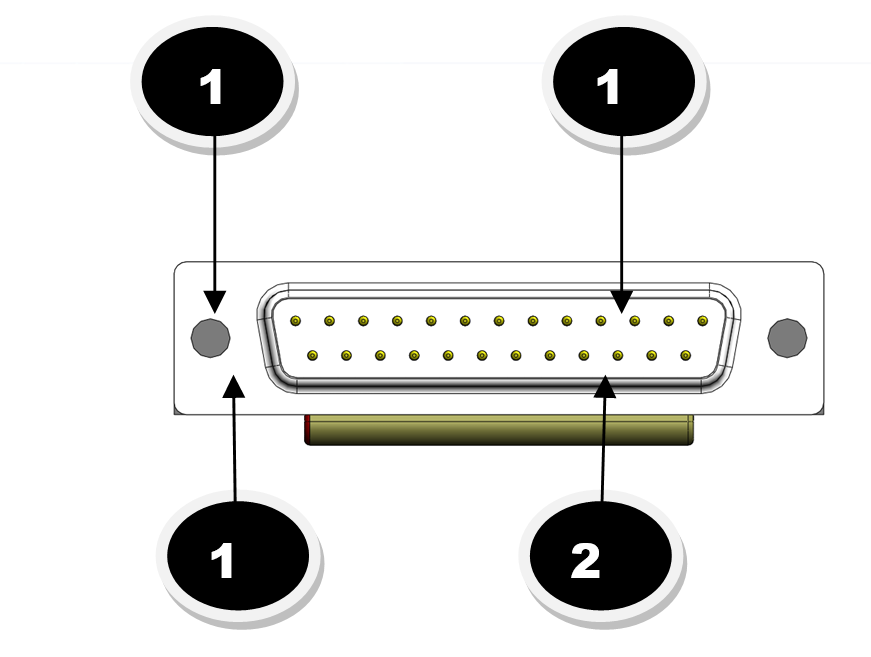
TABLE 1.5 I/O INPUT CONNECTIONS
|
PIN |
DESCRIPTION |
|
1 |
[0VDC] Common (pins 2-4) (Customer to supply.) |
|
2 |
START |
|
3 |
RESET |
|
4 |
SELECT BIT-1 (BINARY) |
|
5 |
SELECT BIT-2 (BINARY) |
|
6 |
SELECT BIT-3 (BINARY) |
|
7 |
SELECT BIT-4 (BINARY) |
|
8 |
USER INPUT (programmable) |
|
9 |
USER INPUT (programmable) |
|
10 |
[ 0VDC] Common (5-9) (Customer to supply.) |
|
13 |
E-Stop (must be held high for normal operation when this option is enabled) |
|
|
|
Created with the Personal Edition of HelpNDoc: Streamline Your Documentation Process with a Help Authoring Tool